Tag Archives: narrow gauge

A Pair of CDR ‘Twins’

Paul Titmuss


The twins: the van on the left is from Ninelines, that on the right (and next to the loco in the next photograph) is the Alphagraphix/Inscalemodels combination

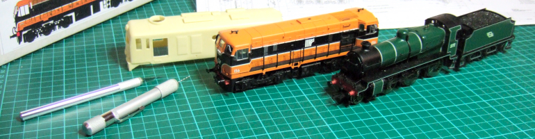
The "twins:" the van on the left is from Ninelines, that on the right (and next to the loco in the next photograph) is the Alphagraphix/Inscalemodels combination

Maybe surprisingly there are two kits available for the County Donegal Railways 1893 Oldbury vans in 4mm scale. One is the ‘heritage’ plastic kit by Ninelines, introduced around 1989, the other a card kit by Alphagraphix from around 2002. I’d built the Ninelines kit many years ago when I had first started in 00n3. Very straightforward as you would expect and it is a shame that with the demise of Ninelines it may no longer be available. I was fortunate to acquire the card kit for this van as I wanted to use it for the Inscalemodels brass chassis kit designed for this van (and as a replacement for the basic Ninelines chassis).Care is needed in cutting out the parts for the card kit. I find the corners of the framing the most challenging. I followed the instructions provided. In 4mm scale I would not advise any backing of the timber framing with scrap card, everything seems to fit well without. The painting of the card edge can also be tricky. I used Humbrol enamel paint, applied along the edge, from the back, with a fine brush. It would be helpful to have a suggestion of suitable paint colour to use in the instructions as I’m very poor at colour mixing. With a range of greys in front of me I eventually opted for Humbrol Slate Grey, No 31, which seems a near match for this kit. Other kits will vary.

I’d already soldered together the frames, etc provided by Inscalemodels. They needed shortening a little at each end to fit the van body. I backed them with balsa wood so that they could be stuck to the mount board that formed the floor of the van. The masters of brass out there would do a more professional job I’m sure. I finished the chassis using 10.5mm diameter wheels from Alan Gibson. The roof is made from corrugated plastic-card glued to a balsa former and is removable. The vacuum pipes were completed with brass wire, wrapped around with iron wire for the hose, acceptable at a glance. A brass pin soldered to the pipe fits through a hole drilled into the end of the van and, glued from the inside, will hopefully hold the pipe in place without causing damage to the card if it gets knocked.

Shunting at Lispole... now how did two CDR vans get this far?

Shunting at Lispole... now how did two CDR vans get this far?

Close-up of the Alphagraphix kit

Close-up of the Alphagraphix kit

The Alphagraphix card kit takes much longer to produce and I’ll let the reader judge whether it’s been worthwhile! I find building three card kits a year is enough, though there is something addictive about them and they definitely should not be discounted. I’m currently building the CDR bogie wagon by Alphagraphix, and there is that wonderful combination of a card kit with soldering to tax one’s skills!

[Paul also tells me that his  Annascaul, Lispole and T & DR web sites have gone down with the expiry of his freeserve web address. The preamble from Freeserve said this would not happen, but then it became Wanadoo, and then Orange so he assumes that the rules have changed. At some point in the future he hopes to resurrect them, in a superior format.  Ed]

Leave a comment

Filed under Modelling

Something a Bit Bigger…


I am grateful to Neil Ramsay for these photos of his wonderful 15mm scale model of CDR  six-wheel saloon no 1. The bodywork is cut from plywood, built up in layers to produce the panelling, the  use of real wood in this scale gives the  effect of the grain, and imparts more ‘atmosphere’ to the model. The axle-guards were gravity cast (from Neil’s masters) in white metal by John Campbell, who also provided the lamp-tops.

The interior is fully detailed, always a good idea for saloon stock, and especially in the larger scales. The internal mirrors are cut from old CDs with real French-polished woodwork and carpeting from dolls’ house wallpaper. The dining chair is a dolls house model in 1/24th scale, with a new seat from Das modelling clay. They are not really proper scale models of the originals, but give the right ‘feel’ when looking through the windows.

The chassis is built with  simplified Cleminson units,  a mixture of home made components  and sprung bearing assemblies from Ron Grant. The centre wheel assembly is shifted sideways by the linkage to the outer wheels. The problem in a model like this is trying to achieve maximum lateral movement of the centre wheels, as this determines the minimum radius (just about 5’) it will go round.  Springing greatly improves the running: in fact Neil’s  six-wheelers run better than bogie coaches and suffer less from buffer lock as the ends don’t stick out so much on curves. Wheels are Slaters gauge 1 split-spoke 37mm diameter. Neil recommends  Slaters 31mm diameter spoked wheels for the 2’ CDR and LLSR wheels. These wheels are coarse scale G1 and work really well in the garden.

1 Comment

Filed under Modelling

Wagon Portrait

CDR Oldbury open in 15mm scale, built by Neil Ramsay

CDR Oldbury open in 15mm scale, built by Neil Ramsay

The wagon uses Slaters 37mm diameter G1 split spoke wheels and couplings, and axelguards from John Campbell.

Leave a comment

Filed under Modelling

Scale Drawings – Ballymena & Larne 2-6-0ST

Ballymena & Larne Railway Beyer Peacock 2-6-0ST (originally published in Railways, no. 44, Dec. 1943, page 190

Ballymena & Larne Railway Beyer Peacock 2-6-0ST (originally published in Railways, no. 44, Dec. 1943, page 190

Leave a comment

Filed under Scale Drawings

Getting Started On Soldering: The TDR Three-Plank Wagon Kit

Paul Titmuss


It is evident from discussion that there are a number of modellers who want to progress to brass and nickel silver kits, but are loathe to make the jump because there seems to be nothing for the ‘beginner’ to try their soldering skills with first. I was at this stage once and still find soldering outside my ‘comfort zone’, but am becoming more skilled and increasingly confident, though I don’t profess to be an expert. The Tralee & Dingle three-plank wagon, available from Worsley Works is, I believe, a good starting point. It is low cost (£4.50 + £1.50 P&P), can be used for either 009 or 00n3, and if you bottle out can be stuck together with glue (I have built a wagon using epoxy resin). It is designed to fit the Parkside Dundas Tralee & Dingle van chassis. I am attempting to build Annascaul Station on the Tralee & Dingle Light Railway and whilst there is a lot of stock available from model manufacturers several key items are not catered for, the three-plank wagon being one of them. With the help of published and unpublished photographs (generously loaned by David Rowlands) I drew diagrams for the wagon and sent them to Allen Doherty at Worsley Works, who used them to  create the necessary brass etches for the kit. The best published photograph of a three plank wagon (and one I relied upon heavily in the diagrams) can be found in The Tralee & Dingle Railway by David Rowlands, published by Bradford Barton, p75. By the time of closure each of the remaining wagons had been reconstructed so there were differences between them.

Photo #1: This shows the etch, constructed wagon body and the completed wagon on Parkside Dundas T&D van chassis.

Photo #1: This shows the etch, constructed wagon body and the completed wagon on Parkside Dundas T&D van chassis.

Photo #2: The set up used for soldering. An Antex 25W soldering iron and stand, flux and 145° solder. I do not usually go to the extreme of soldering outside, but on a nice day its quite pleasant, but dont drop any parts!

Photo #2: The set up used for soldering. An Antex 25W soldering iron and stand, flux and 145° solder. I do not usually go to the extreme of soldering outside, but on a nice day it's quite pleasant, but don't drop any parts!

Photo#3: The first job is to tap in the bolt heads. I do this with a pin whilst the brass etch is resting on a piece of hardboard. A light tap is enough. When this is done flux and solder (tin) the insides of both sides and ends. When completed cut the parts out of the fret and clean up the rough edges with a file.

Photo#3: The first job is to tap in the bolt heads. I do this with a pin whilst the brass etch is resting on a piece of hardboard. A light tap is enough. When this is done flux and solder (tin) the insides of both sides and ends. When completed cut the parts out of the fret and clean up the rough edges with a file.

Photo #4: Line up the pieces, ensuring that the outside overlaps the inside section equally at both ends. I have recently acquired some little clips to help. The work is then held in a vice.

Photo #4: Line up the pieces, ensuring that the outside overlaps the inside section equally at both ends. I have recently acquired some little clips to help. The work is then held in a vice.

Photo #5: Flux is applied to the top edge and then solder run along the joint.

Photo #5: Flux is applied to the top edge and then solder run along the joint.

Photo #6: When happy with the join put the side or end on the work surface, inner side up and then apply heat from the soldering iron to help the tinned sides make a better bond. There should be a little solder on the tip of the iron to help with the transfer of heat.

Photo #6: When happy with the join put the side or end on the work surface, inner side up and then apply heat from the soldering iron to help the tinned sides make a better bond. There should be a little solder on the tip of the iron to help with the transfer of heat.

Photo #7: To join a side end place upside down on the work surface. The end piece goes inside the wagon side. Make sure the joint is fluxed. I hold the work in place with Blu-tack®. I also used some fine graph paper to help get the pieces square. The join between the two parts can then be soldered.

Photo #7: To join a side end place upside down on the work surface. The end piece goes inside the wagon side. Make sure the joint is fluxed. I hold the work in place with Blu-tack®. I also used some fine graph paper to help get the pieces square. The join between the two parts can then be soldered.

Photo #8: When both pairs of sides and ends have been joined I then solder up the remaining corners an the basic body shell is complete. You may wish to trial fit the chassis floor at this stage (see photo #11).

Photo #8: When both pairs of sides and ends have been joined I then solder up the remaining corners an the basic body shell is complete. You may wish to trial fit the chassis floor at this stage (see photo #11).

Photo #9: The strapping can then be applied. These pieces can be easily fixed using epoxy resin. If you attempt to solder the straps make sure they are tinned on the fret first, and would be an idea to apply the straps to the work before the sides are built up. The tall end straps are raised from the body and I glued these to strips of plastic card, and then these in turn were glued to the wagon ends.

Photo #9: The strapping can then be applied. These pieces can be easily fixed using epoxy resin. If you attempt to solder the straps make sure they are tinned on the fret first, and would be an idea to apply the straps to the work before the sides are built up. The tall end straps are raised from the body and I glued these to strips of plastic card, and then these in turn were glued to the wagon ends.

Photo #10: The corner plates need to careful bending in a vice. I held them between two rulers and pressed the edge over with a small piece of 1 x 1 timber. On the actual wagon the short edge went along the side so there is no need to panic if the two edges are not the same length. To complete the door straps lengthen the hinge gap by cutting into the etch. Place a fine piece of wire (not supplied) on the edge of the board (with Sellotape®) and press to shape. If the wire has been tinned and the job fluxed this is an easy soldering job. Cut off spare wire and etch before fixing in place. The door straps should just overlap the edges for the door sides.

Photo #10: The corner plates need careful bending in a vice. I held them between two rulers and pressed the edge over with a small piece of 1" x 1" timber. On the actual wagon the short edge went along the side so there is no need to panic if the two edges are not the same length. To complete the door straps lengthen the hinge gap by cutting into the etch. Place a fine piece of wire (not supplied) on the edge of the board (with Sellotape®) and press to shape. If the wire has been tinned and the job fluxed this is an easy soldering job. Cut off spare wire and etch before fixing in place. The door straps should just overlap the edges for the door sides.

Photo #11: The Parkside Dundas chassis can be made up. The floor needs to be carefully sanded to size, a tad off each end (including the sole bars) and a little more off the sides (circa 0.25mm each side) so that the body fits the floor (it might be an idea to fit this before the strapping is applied as a dry run). Dont get too carried away as it is easy to remove too much floor. Next the body is glued to the floor. Vacuum pipes need to be sourced (or those that come with the chassis can be used) plus couplings of choice added to complete construction. It is best to give the brass a coat of etched brass primer before painting and weathering to taste. Hopefully, you have now completed a first successful taste of soldered kit construction. Do remember that if you bottle out with the soldering then the kit can be glued together, so it wont be wasted.

Photo #11: The Parkside Dundas chassis can be made up. The floor needs to be carefully sanded to size, a tad off each end (including the sole bars) and a little more off the sides (circa 0.25mm each side) so that the body fits the floor (it might be an idea to fit this before the strapping is applied as a 'dry run'). Don't get too carried away as it is easy to remove too much floor. Next the body is glued to the floor. Vacuum pipes need to be sourced (or those that come with the chassis can be used) plus couplings of choice added to complete construction. It is best to give the brass a coat of etched brass primer before painting and weathering to taste. Hopefully, you have now completed a first successful taste of soldered kit construction. Do remember that if you bottle out with the soldering then the kit can be glued together, so it won't be wasted.

Acknowledgements:
Thanks to David Rowlands for the loan of photographs, Allen Doherty for the preparation of etches and Simon Starr for exchange of ideas.

Addendum:
If anyone has already purchased one (or more) of the three-plank wagon kits there was an error with the original production etch. The right hand door straps are now available on receipt of an SAE from Worsley Works. My third wagon was completed with these.

2 Comments

Filed under Modelling